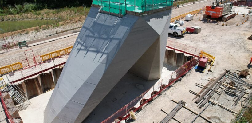
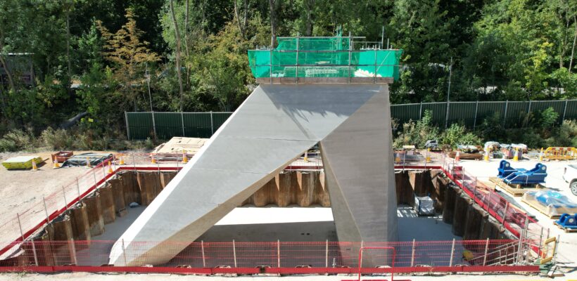
The fixed buttress piers had significant architectural features and were shaped as an asymmetrical angular arch with the 8 faces on each leg tapering over the height of the pier. The position of joints and ties were important considerations and had to be agreed with the customer.
Altrad RMDK worked closely with their customer to provide a flexible solution that was efficient to use. It consisted of 79 unique quadrilateral panels ranging in weight from 82kg to 1550kg that were bolted together at the changes in direction of the pier.
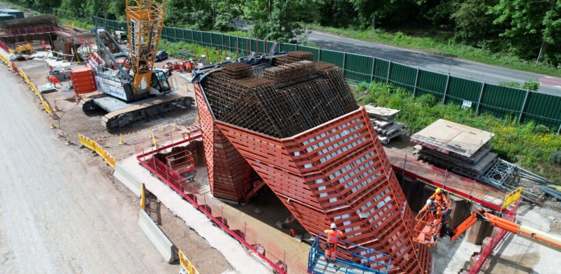
The panels were designed as composite two-way spanning structure with folded horizontal channels and vertical flats. The completed structure utilised 20mm ties and hoop action to contain the significant concrete pressures. The vertical concrete loads from the arch were resisted by a specially designed support structure.
Due to limited access and mechanical lifting options an innovative solution had to be developed to strike the equipment. Altrad RMDK designed the support frame with special wedges which when struck lowered the frame onto integral wheels and allowed it to be rolled out leaving the panels held in place by the tie bars. A special full width lifting beam, featuring a rotating circular tube was then used to lower the panels to the ground.
The analysis of the formwork was one of the most challenging ever undertaken by Altrad RMDK and pushed the boundaries of what is possible with conventional software. An elastic analysis was carried out on the complete structure and contained over 13,000 individual members.
Speed of detailing and fabrication were critical to the success of the project and a great deal of thought went into keeping it to a minimum. To simplify fabrication the folded channels and vertical flats were slotted so that their relative positions were fixed reducing setting out time and the need for jigs. Electronic DXF files were created for every component in such a way that they could be input directly into the laser cutter.
The DXF files were the primary data with the drawings just being used for identification. This reduced detailing time as only principal dimensions had to be shown. Each DXF file included an identification number which was etched on by the laser cutter which aided assembly.